Follow the nine steps above to learn how to prepare the perfect 2D technical drawing. Once ready, export it as a PDF file and attach it to our online submission form when requesting for a quote or placing an order.
")
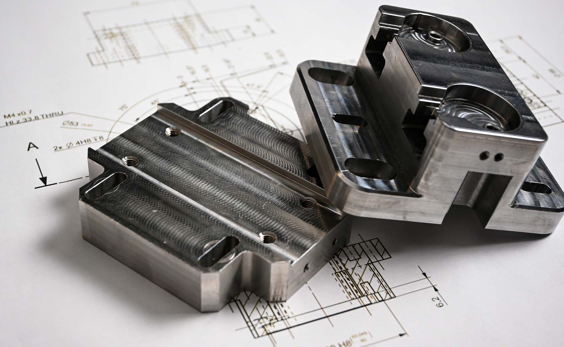
While 3D CAD files are quite comprehensive in what they can communicate to CNC machines, technical drawings remain important in sourcing parts, as they contain information that a 3D model can’t convey. This includes: internal or external threads, features with non-standard tolerances, and surfaces with specific surface finish requirements.
Even if your design doesn’t include these features, it’s generally good practice to include a technical drawing along with your 3D CAD when sourcing parts. This information is necessary to ensure that parts are manufactured to the required specifications, fit and function correctly, and meet the quality and reliability standards of the final product.
So, how do you prepare a perfect technical drawing for manufacturing? We’ve listed 9 main steps below.
Before we begin, select your template. Standard ASTM, DIN, and ISO templates are available. You can also create a custom template, but ensure that it includes all the necessary details.
1. Add orthographic views
Orthographic views are two-dimensional depictions of your part from different primary views — front, left, right, top and back views. These views convey essential information about your part’s geometry, dimensions, and tolerances. 3D drawings don’t show enough detail — orthographic projections help overcome that problem.

Remember to leave sufficient space to add the dimensions. And avoid excessive use of hidden lines as these can make the drawing confusing and disorganized.
2. Add detail or section views accordingly
In cases where a part is highly complex, contains hidden features, or has challenging dimension, it is good practice to add section views. It is a 2D projection of a part when it is cut through, which enables the manufacturer to visualize intricate dimensions or concealed details (or features) that may not be apparent when viewed externally.
3. Add isometric view (where possible)
The isometric view is a 3D pictorial representation of your part on a 2D surface. It shows your part rotated 45° about the vertical axis, and 35.264° about the horizontal. This view makes it easier for the machinist to understand your part’s geometry and installation direction.

While the isometric view isn’t always necessary, we recommend including it in technical drawings whenever there is space — particularly for parts with complex geometries that cannot be easily interpreted from the orthographic views alone.
4. Place construction lines
Add construction lines on all views for reference purposes — this includes centerlines, centre marks, and cutting lines.
5. Add dimensions
It is critical to include dimensions to your technical drawings. Start off with the most important dimensions on the orthographic views. Ensure that all the dimension lines and figures are clearly visible and do not cross each other or the drawing.
6. Specify the location, length, size of all holes and threads
Hole callouts: Use call outs instead of dimensioning all the aspect of the hole. A typical hole callout specifies the hole depth and diameter, the number of identical holes, and the presence of a counterbore or countersinks, along with the depth of these features.
Thread specifications: be sure to assign each thread and its relevant thread size (rather than its dimensions in millimeters).
7. Add tolerances to critical features
By default, HLH Rapid applies standard tolerances — controlled to ISO-2768 medium for plastics and ISO-2768 fine for metals — unless higher tolerances are specified. We recommend including tolerance values in all holes, threads, and other critical parts.
8. Fill Out Title Block
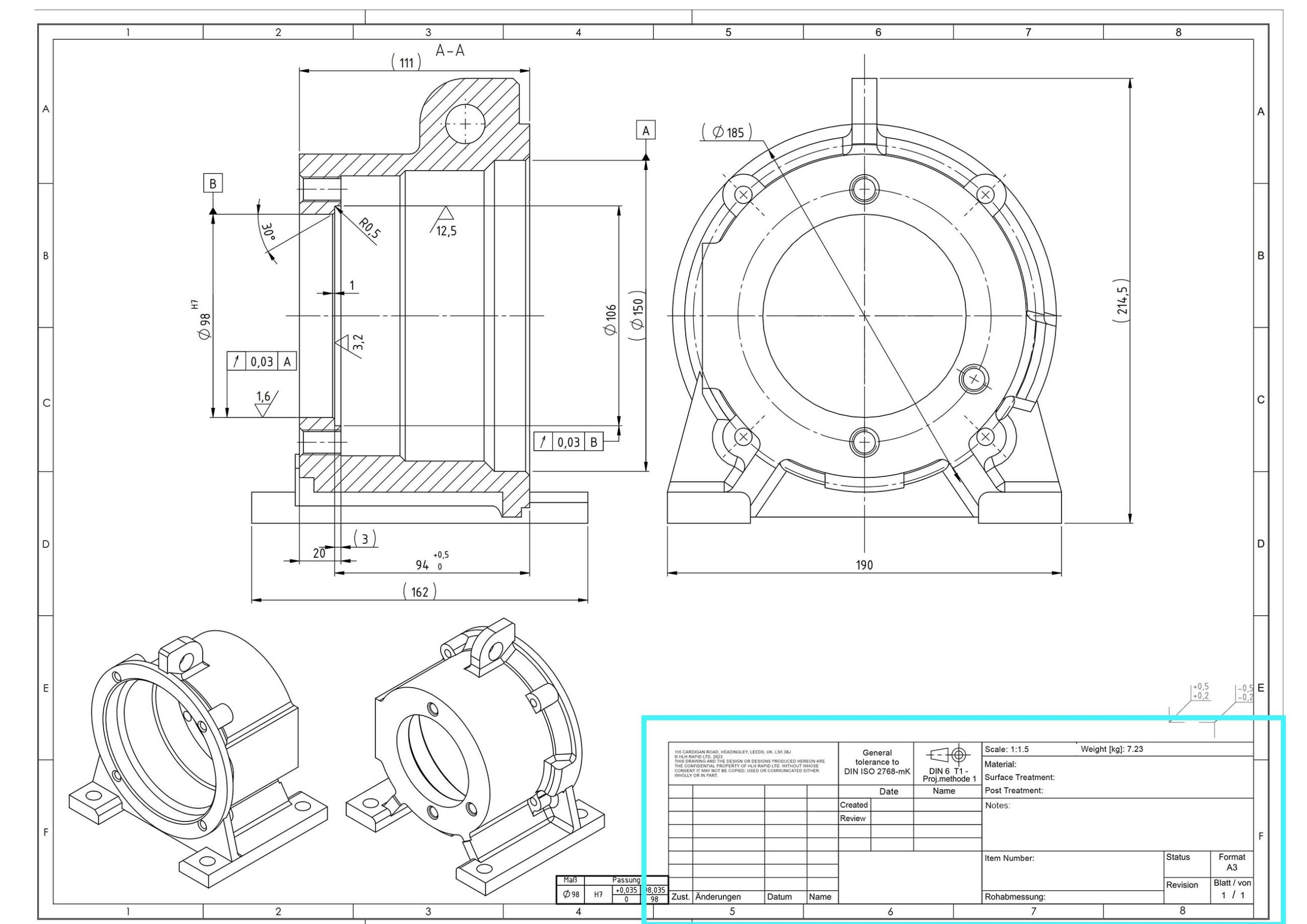
The title block contains basic information about the part, such as the part name, material, and surface finish. Even if you’ve communicated these details to the manufacturer beforehand, it is good practice to fill it out in the title block.
The title block should also contain details like the scale of the blueprint, standard tolerances used, copyright statement, designer’s name and company information.
9. Note to Manufacturer
This can be included anywhere in the technical drawings to communicate additional information you think might be helpful for the manufacturer.
The ultimate purpose of a 2D technical drawing is to provide machinists and engineers with all the necessary information and clear instructions to ensure that the final product meets the intended specifications. As such, it’s important to make it simple, make it neat and make it universally understandable. This helps avoid any errors, complications or surprises down the road.
Follow the nine steps above to learn how to prepare the perfect 2D technical drawing. Once ready, export it as a PDF file and attach it to our online submission form when requesting for a quote or placing an order.