Understanding tolerances in CNC Machining is vital for the form, fit, function of the final part. So, what’s the best way to achieve optimal results? This Machining Tolerance Guide will walk you through everything you need to know about CNC tolerances, including:
While CNC machines are extremely precise, achieving absolute perfection with any process is impossible—there will always be a small dimensional variation between the finished part and the original drawing. The amount of deviation allowed in a part’s dimension from the intended design is known as machining tolerance. These tolerances are critical, as they ensure machined parts fit together correctly, function as intended and meet required performance standards.
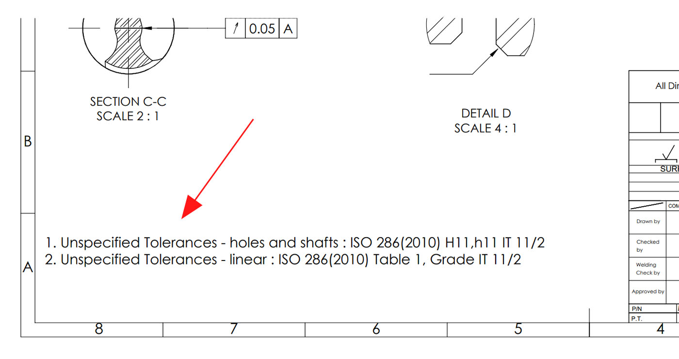
Tolerances specify the maximum allowable dimension, known as the upper limit, and the minimum allowable dimension, known as the lower limit. They are often expressed in the format ±0.x mm. If the actual size of a part falls outside these limits, the part is considered unusable and must be rejected. For example, if a bolt is designed to be 100 mm long and specific to have a tolerance of ±0.05 mm, its actual length can be anywhere between 99.95 mm (lower limit: 100 − 0.05) and 100.05 mm (upper limit: 100 + 0.05) and still be considered acceptable.
ISO 2768 is an international standard that provides general tolerances for linear and angular dimensions in millimeters, so you don’t have to specify a tolerance for every dimension. It divides tolerances into four classes:
The chart below provides the general tolerances for these classes.
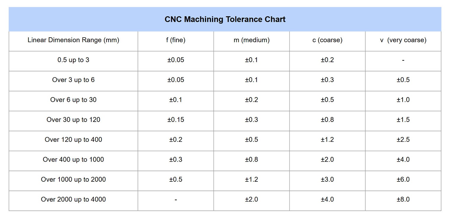
Default CNC Tolerances — Unless specified on the 2D technical drawing, the parts will usually be machined according to a general tolerance grade. At HLH, standard tolerances are controlled to ISO 2768-1 medium (m) for milled and turned parts, generally around ±0.005″ (0.13 mm).
High-Precision CNC Tolerances — For applications requiring greater accuracy, such as aerospace or high-performance automotive components, we can machine metal parts to tolerances as tight as ±0.001″ (0.025 mm) or better. This level of precision is considered a tight tolerance in machining.
Tightest Tolerance Achievable with CNC — For very specialized parts like surgical equipment and implants, certain CNC shops equipped with advanced machines and techniques can achieve extremely tight tolerances, ranging from ±0.0002″ (0.00508 mm) to ±0.0005″ (0.0127 mm). However, it is quite rare to require such extreme precision.
Part geometries and machining processes can vary significantly from project to project, so tolerances can be specified using different systems ad not just the standard ±0.x mm format.
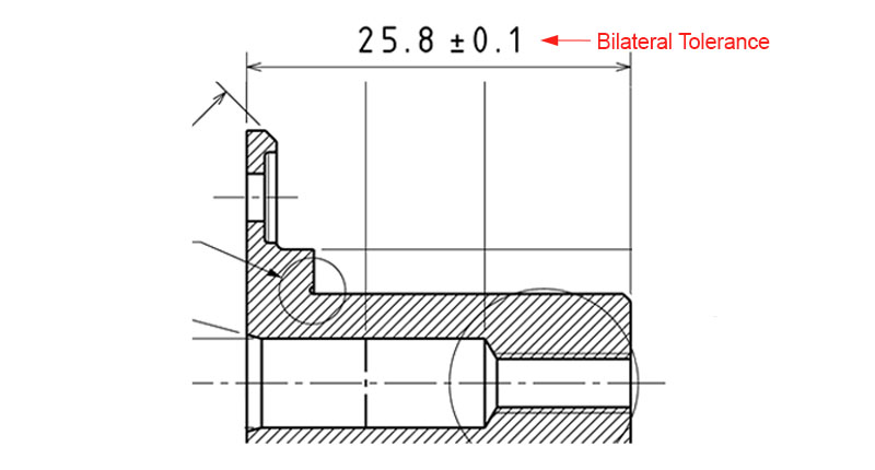
Bilateral Tolerance:
This is the more commonly used system, where the allowed variation is applied equally above and below the basic (nominal) dimension. For example, if a shaft’s basic size is 25.8 mm and the tolerance is ±0.1 mm, its upper limit is 25.9 mm and its lower limit is 25.7 mm.
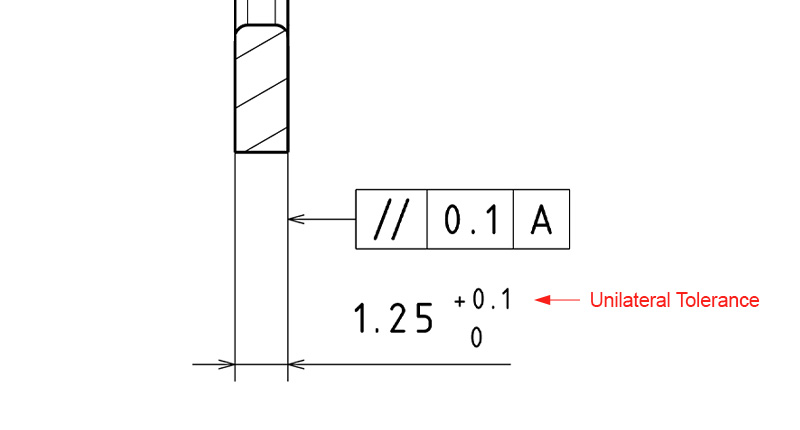
In a unilateral tolerance, the basic size of the component is the same as either the upper limit or the lower limit, and the permissible variation is only in one direction—either entirely positive or entirely negative, but never both. For example, if a pin has a basic diameter of 1.25 mm and a unilateral tolerance of +0.1 mm, the acceptable dimension would range from 1.25 mm to 1.35 mm. Any value below 1.25 mm or above 1.35 mm is out of tolerance.
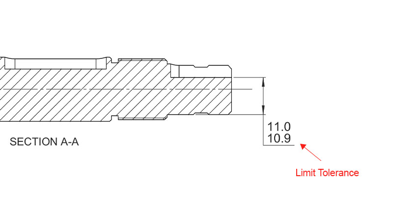
Limit Tolerance:
Limit tolerancing uses a straightforward system that eliminates the need for calculations. For example, a shaft with a nominal diameter of 10.95 mm and a bilateral tolerance of ±0.05 mm can be directly expressed using limits as 10.9–11.0 mm. This system is less commonly used in engineering drawings and is typically reserved for small or simple parts.
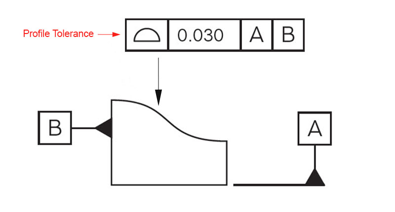
Profile tolerancing is expressed using the profile symbol, which looks like a semicircle (half oval) in 2D engineering drawings. It controls the shape of a curve so that the actual edge of the part lies within a specified tolerance zone around the nominal profile. For example, if a line profile tolerance of 0.03 mm is specified, the actual curved edge of the part must lie entirely within a band 0.03 mm wide centered on the nominal curve (±0.015 mm on either side).
Tight tolerances demand specialized cutting tools and longer machining times, which can significantly increase part costs. In fact, only about 1% of parts require tolerances in the ±0.0002″ to ±0.0005″ range. And often, it’s just certain features that need ±0.001″ (0.025 mm) or tighter. Unless absolutely necessary, avoid “over-tolerancing” and stick to standard tolerances wherever possible.
Use tighter tolerances only on critical features that affect assembly, fit or function. Keep non-critical features at standard tolerances to save cost and time.
When two assembly parts mate together, their dimensions combine to create a final measurement. If the total is over or under the intended value, the variation can cause fit or function issues. Stack-up analysis — often using a worst-case scenario calculation — helps prevent these problems.
If your project uses tolerances that differ from the company’s or industry’s default standards, include a tolerance table directly on the 2D drawing. This ensures machinists and inspectors know exactly which limits apply to each dimension.
The expectation of tolerance should be in line with the material’s machinability. Soft, flexible or abrasive plastics are more challenging to machine to tight tolerances, whereas metals, more rigid plastics and certain composites can achieve higher precision in CNC. For standard plastic parts, machinists commonly use ISO 2768-1 Medium, while for metals and other rigid materials, ISO 2768-1 Fine is generally used.
Need precision machined parts or assemblies for your next project? Send across your STP (.step) file and 2D drawing with the critical tolerances specified (if any) to us at info@hlhrapid.com, and our team will get back with a free quote within 24 hours. If you want to learn more about CNC machining with HLH, simply visit our CNC Services Page.