Investing in injection moulding can be very costly. It would be a waste to invest in the process only to encounter defects and unwanted outcomes, which in some cases not only affect the aesthetics but also the structural integrity of the part. Some defects are less severe, while others can be very costly to remedy. In this article, we will go through the top 10 most common injection moulding defects, their severity, root causes, and solutions to prevent them.
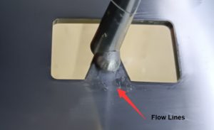
Flow lines are visual defects—dents, divots, depressions, or craters—on the surface of a moulded part. Manifesting as wavy lines, patterns, or streaks on the surface of the moulding, flow lines generally occur when molten material flows unevenly or when some areas cool faster than others. While they are commonly considered less serious injection moulding defects because they typically don’t affect tolerance or the structural integrity of a moulded part, they can be unsightly and may be unacceptable for visually critical parts.
Causes:
Solution:
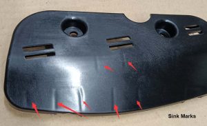
As the name suggests, sink marks are depressions or unwanted dents that form on the surface of an injection-moulded part during the cooling process. Sink marks occur when the outer layer solidifies before the inner layer, causing a depression as the inner material continues to cool and contract. Although considered less serious since they do not affect the strength or function of the part, sink marks are a common defect and are visible on the surface.
Causes:
Solution:
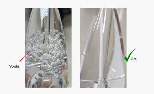
Vacuum voids, bubbles or air pockets are trapped air bubbles that appear on the inside the finished moulded part. Quality control professional typically consider voids as a more minor defect, although, in some cases if a large number of voids form, it can be considered a serious defect, as it can weaken the moulded part.
Causes:
Solution:
Blisters are pockets of trapped air that can look like a bubble on parts. However, unliked trapped air bubbles under the surface of the part, a blister is a raised or layered bubble on or near the surface of a moulded part. Blistering is often caused by tools or melted resin that is too hot and does not have adequate time to cool.

Causes:
Solution:
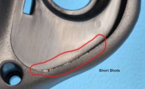
Short shot is considered a major defect in injection moulding. Short shots defect occurs when the material does not completely fill the mould. The most common cause of short shots is flow restriction resulting from narrow or blocked gates. Sometimes the material is too viscous or the mould is too cold to allow the molten material to completely fill the mould before cooling. And other times trapped air pockets may be hindering proper flow or injection pressure may be inadequate.
Causes:
Solution:
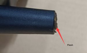
Attempting to “fix” short shots can result in flash defects — the opposite of short shots. Flash, in injection moulding, refers to the excess material that leaks out of the mould cavity during the injection process. This defect most often results from using a poorly-design or degraded mould, while other causes include improper clamping or excessive injection pressure. Flash is usually subtle but might be considered a major defect if particularly obvious on a product.
Causes:
Solution:
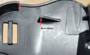
As the name suggests, burn marks appear as black or brown discoloration or streaks on the moulded part. Burn marks are a common injection moulding defect that can be caused by multiple factors, not just high temperatures. Other causes include excessive moisture in pellets or poor mould tool conditions. Although burn mark defects do not affect the structural integrity of the part, they can make the part look worn out and highly unappealing.
Causes:
Solution:
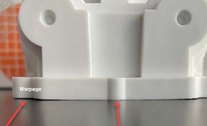
Warps are one of the most common injection moulding defects. Warping is a defect that results in the distortion—bends, twists, or other deformations—of the shape of a plastic part, which becomes apparent after it has been ejected from the mould. Such defect typically appears when there are different cooling rate across the part. If different sections of a part cool and solidify at different rates or times, internal stress, known as “stress creep,” can build up and lead to distortion.
Causes:
Solution:
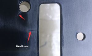
Weld lines, which are sometimes mistaken for flow lines, are injection melding defects that result in a undesired line or seam on the surface of the plastic part. Weld lines form when two or more flow fronts meet and do not fuse properly, often because they are cooler than desired. This commonly occurs around holes or inserts in the mould, or where the flow splits and rejoins. In some cases, weld lines can also create structural weaknesses in the moulded part.
Causes:
Solution:
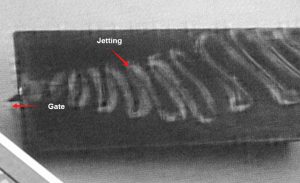
Jetting occurs when the melted plastic is injected too quickly through a restive area (such as a gate, nozzle, or runner) into an open cavity in the mould. This rapid injection can cause the plastic to cool and set before the cavity is fully filled, leading to visible, squiggly flow patterns on the surface of the part. Jetting is considered a major injection moulding defect because it affects the visual aesthetics and can decrease the strength of the part.
Causes
Solution

Get a quote and start your free project review
Tooling and injection moulding are very complex processes that require experience to get right. Our engineering team is fully equipped and experienced in identifying, preventing, and resolving injection moulding defects. When you choose HLH Rapid for your injection moulded parts, you can expect quality, consistency, and accountability throughout the process.
To get started on your injection moulding process, simply submit your 2D and 3D CAD drawings to our site contact form along with your injection moulding project details and we will get back with a quote and thorough DFM prior to order.