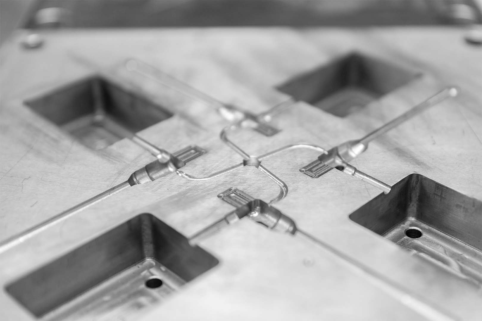
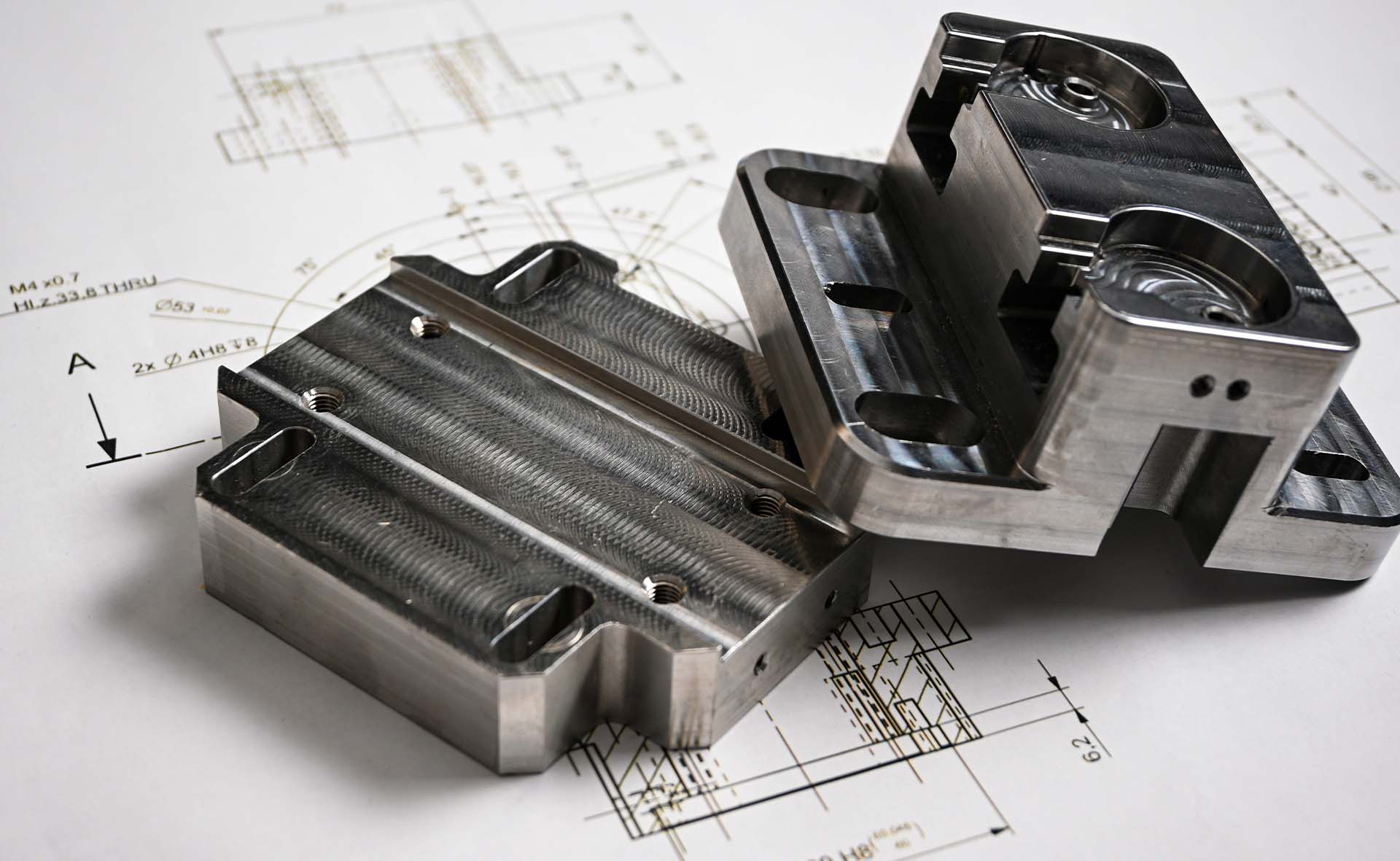
Injection mould gates serve as connections between mould runners and cavity, playing a vital role in mould design. There are several types of gates, each suited to different moulding requirements and designs; failure to choose the correct injection moulding gate can result in several problems during the moulding process and lead to defects. In this article, we will go through the different types of injection mould gates available, why they matter, how to choose an appropriate gate, and design considerations to keep in mind.
An injection moulding gate is a designed opening that controls molten plastics flow into the mould cavity. Essentially, it manages the volume and direction of the flow into the mould cavity. Gates come in various shapes, sizes and types including edge gates, sub gates, and direct sprue gates, which we will discuss further below.

A well-designed and properly positioned gate ensures that the molten plastic evenly reaches every area of the mould before cooling occurs. This helps prevent defects such as incomplete filling, air traps, or uneven cooling, which can lead to deformations like breaks or stress fractures in the final product. It is also crucial to choose an appropriate gate type, as it directly affects part geometry, impacting the overall quality, appearance, and performance of the moulded product. Get an overview of the seven most commonly used gates in injection mould design below.
Edge gates are the most commonly used and straightforward injection mould designs. They are easy to produce when building a mould and are easily modified if needed. They are also ideal for filling larger parts or parts where thicker wall sections could not be avoided. An edge gate can have a larger cross–sectional area compared to other gates. This allows more plastic to flow into the mould and the ability to have longer hold times because of the longer gate freeze.

Key features of edge gates
Submarine gates also known as sub gates, are gates often positioned beneath the mould parting line to allow automatic trimming when the component is injected. It involves using a narrow channel that joins the cavity near the parting line, filling the cavity from below the parting line. Likewise, the draft angle facilitates easy ejection of finished plastic parts without breaking. This gate is ideal for injection moulding small components.

Key features of submarine gates
Cashew gates resemble the shape of a tree nut and are ideal for products that can be disfigured during gate removal. It allows molten plastic to reach places within the mould that cannot be linked or joined by a standard tunnel gate. This gate type is not limited or best fit for any particular plastic resin. Hence, the options remain open if you consider this gate type based on the needs of your product designs. A point to keep mind is that de-gating of a cashew is more difficult.

Key features of cashew gates
In injection moulding, a direct sprue gate is one of the most common, economical, and simple gate. They are typically located directly at the parting line of the mould, at the thickest section of the plastic part, enabling fast injection for large volumes of plastic, with short feeding times and less pressure. Direct sprue gates are well-suited for boxed or shell moulds with a single deep cavity and for producing non-aesthetic parts, making them ideal for manufacturing consumer products and home appliances.

Key features of direct sprue gates
Resembling a fan or wedge-like shape, fan gates are typically positioned at the edge of the part and gradually widen as they extend toward the cavity. They are frequently favoured over traditional gate types, such as sprue or pinpoint gates, for parts with large surface areas or complex geometries. This is because fan gates facilitate smoother filling of the mould cavity, reducing the likelihood of aesthetic or structural issues in the final product.

Key features of fan gates
Like sprue gates, diaphragm gates taper off from underneath the gate, but they typically have a much wider opening. These gates are commonly used for moulded parts with a large open diameter in the middle, as well as for larger parts that need a significant amount of resin fill evenly. The diaphragm gate design is compatible with most resin types and is an ideal option based on the product’s design.

Key features of diaphragm gates
Pin gates are usually placed on the B-side of the mould near the ejector pins, typically the non-cosmetic surface. A pin gate is ideal for three plate moulds with the runner channel located in a different runner plate; the mould flow is split in several directions, leading to the cavity by various gate locations. The gate point is very small, allowing it to be trimmed off by the injection mould opening. It has a high scrap rate due to the large runner, which is a disadvantage.
Key features of pin gates
By strategically choosing a gate type and positioning gates, designers can minimise flow-related issues such as flow marks, weld lines, or uneven shrinkage, resulting in more consistent part dimensions and properties. Here is what you need to consider when designing gate sizes, placements and shape:
HLH Rapid takes the guesswork out of injection moulding for prototyping. Our engineers design and build custom moulds and parts using your CAD drawings and select the proper gate for your design prior to tooling and manufacturing. Simply submit your CAD drawings and project details like quantity, material and surface finish (if any) to our site contact form here, and our team will get back with a quote within 24-48 hours.
