Plastic parts are needed everywhere, and Injection Moulding is the most popularly manufacturing method for producing these parts. It is neither subtractive or additive but a formative process that shapes molten plastic within a mould cavity, producing complex parts in a single step with high repeatability and precision, making it ideal for mass production.
Plastic injection moulding is primarily a mid-to-high volume part production process, but it can also be adapted for low-volume runs using a technique called rapid injection moulding. When done right, it produces high-quality parts with excellent surface finish and reliable mechanical properties.
To take full take advantage of this technology, it is important that your 3D model follows a set of established design guidelines. This article covers key injection moulding process considerations, design guidelines, cost reduction tips and summary of the best design practices.
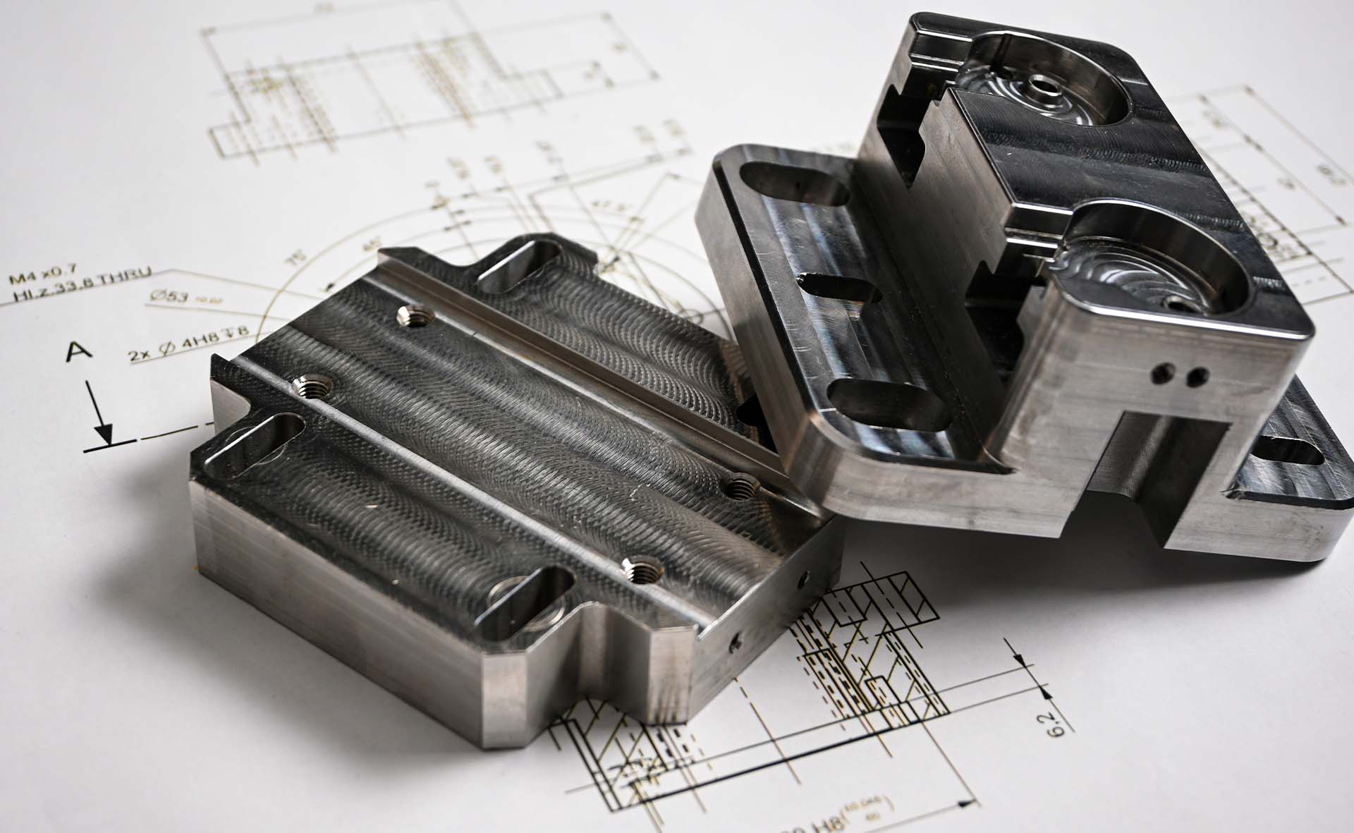
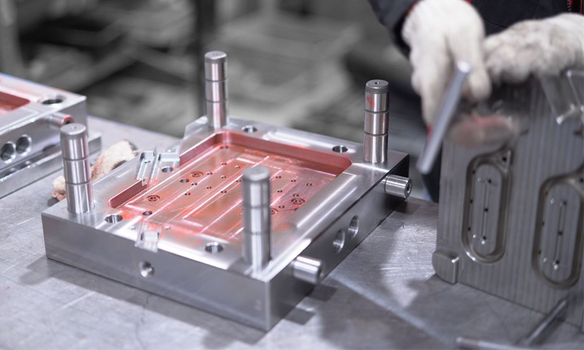
The process uses three essential components—the mould (or tool), resin material, injection mould machine. Using a CAD model (.STEP format preferred), a mould is created and machined with precision to form the part’s features. Next, it is installed into an injection mould press and molten plastic is injected into the mould tool under high pressure. The part is then cooled, ejected and the process repeats.
Injection Moulding Process Considerations
Use a uniform or constant wall thickness throughout the part (if possible) and avoid overly thick walls to prevent parts from warping or sinking. Designing wall thickness can be tricky and differ depending on material choice. Generally, staying within a 1.2–3.0 mm thickness is safe for most materials.
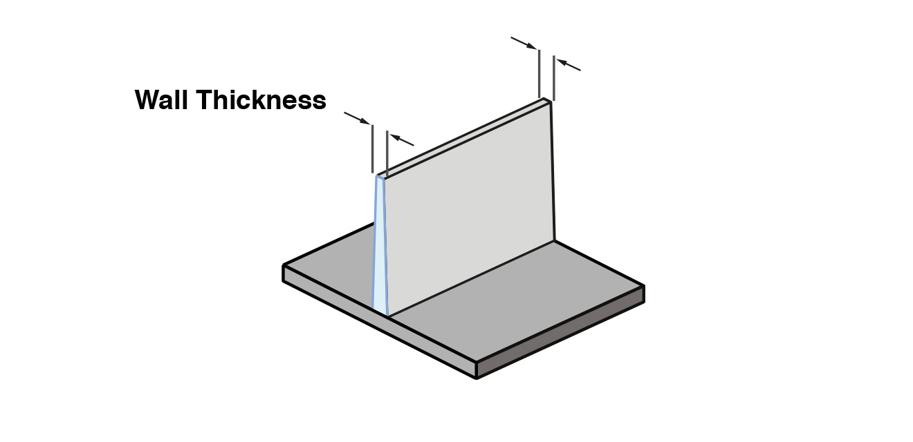
Recommended wall thickness for common resins available at HLH Rapid:
| Common materials | Recommended wall thickness (mm) |
| ABS | 1.2 – 3.5 |
| Acrylic (PMMA) | 0.7 – 3.8 |
| PC/ABS | 1.2 – 3.5 |
| Polycarbonate (PC) | 1.0 – 4.0 |
| PEEK | 1.0 – 3.0 |
| Polyethylene (PE) | 0.8 – 3.0 |
| POM | 0.8 – 3.0 |
| Polypropylene (PP) | 0.8 – 3.8 |
| Nylon (PA) | 0.8 – 2.9 |
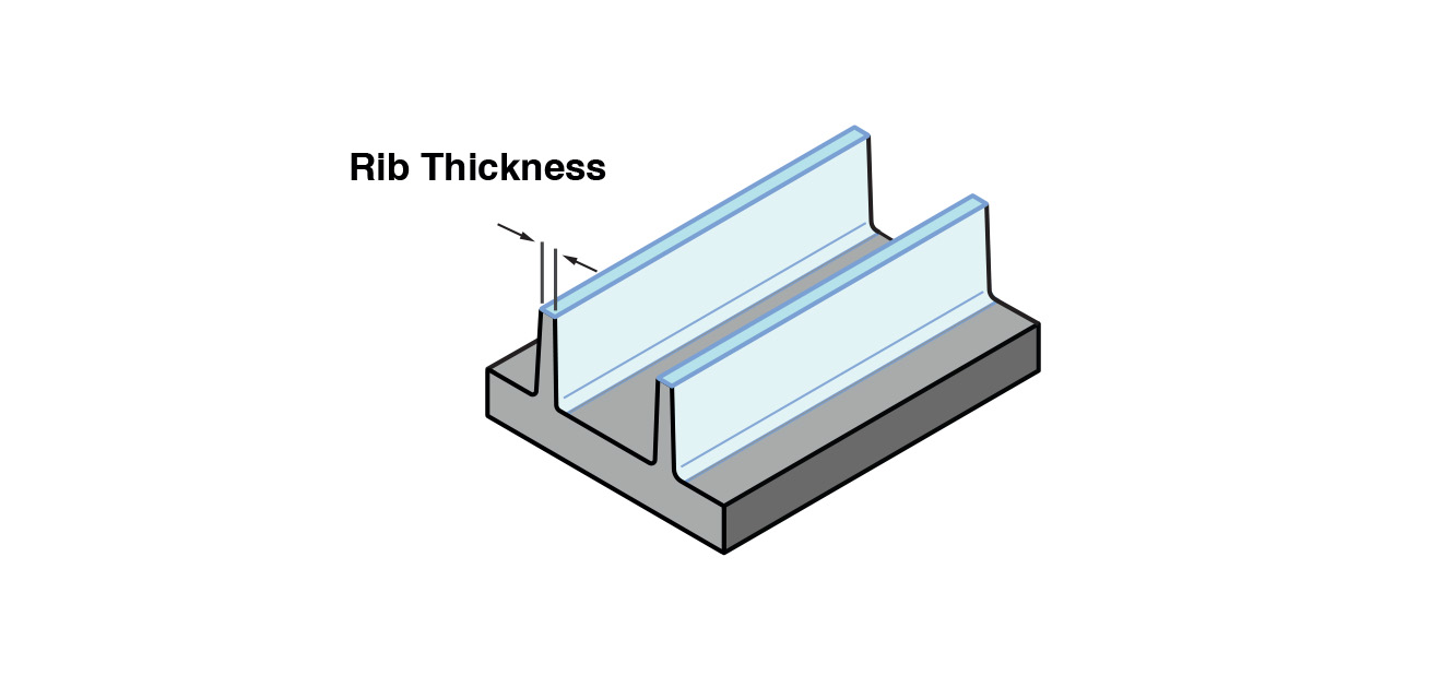
Ribs are thin, raised features incorporated in injection moulded parts to increase stiffness and strength. However, if not properly designed, ribs can make parts prone to sink marks. The maximum rib thickness should not exceed 0.5 times the nominal wall thickness, and the rib height should be limited to less than three times its thickness.
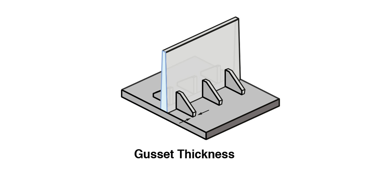
Gussets are rib-like features that do not extend all the way across a surface. They are used to increase strength and stiffness at stress concentrations without adding too much extra material. Keep gusset thickness at 50–60% of the nominal wall thickness to avoid sink marks in parts.
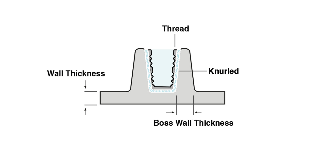
For best results, avoid adding threads directly on your injection moulded part. Instead, threaded inserts can be overmoulded into the part, usually placed in a boss to support the insert. The boss wall thickness should be 60% of the nominal wall thickness to minimise sinking, and the boss height should be less than 3 times the outer diameter, while still providing at least 60% of the screw thread with something to catch on.
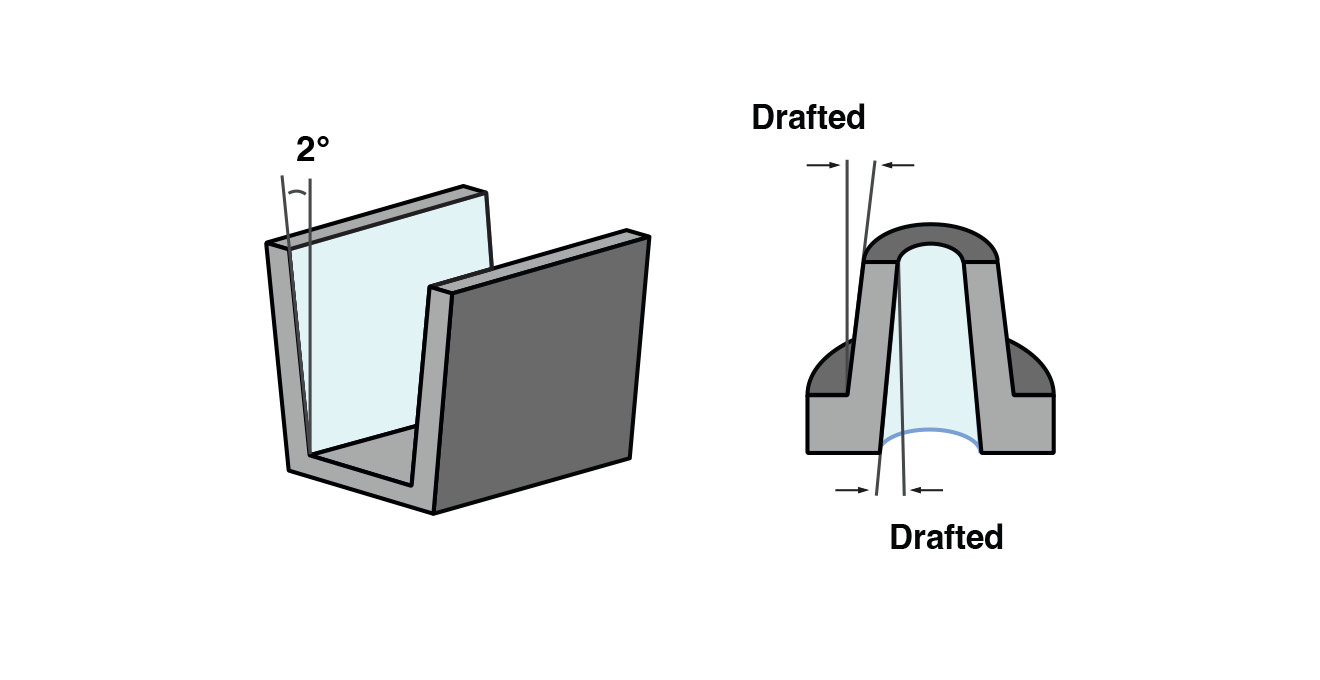
Parts with vertical walls (and no draft angle) are most prone to drag marks. Typically designers apply a draft of 1½ to 2 degree, but to be on the safe side, we recommend a draft of 2° or more. A good rule of thumb is to increase the draft angle by one degree for every 25 mm. For example, for a feature that is 75 mm tall, add a draft angle of 3 degrees.
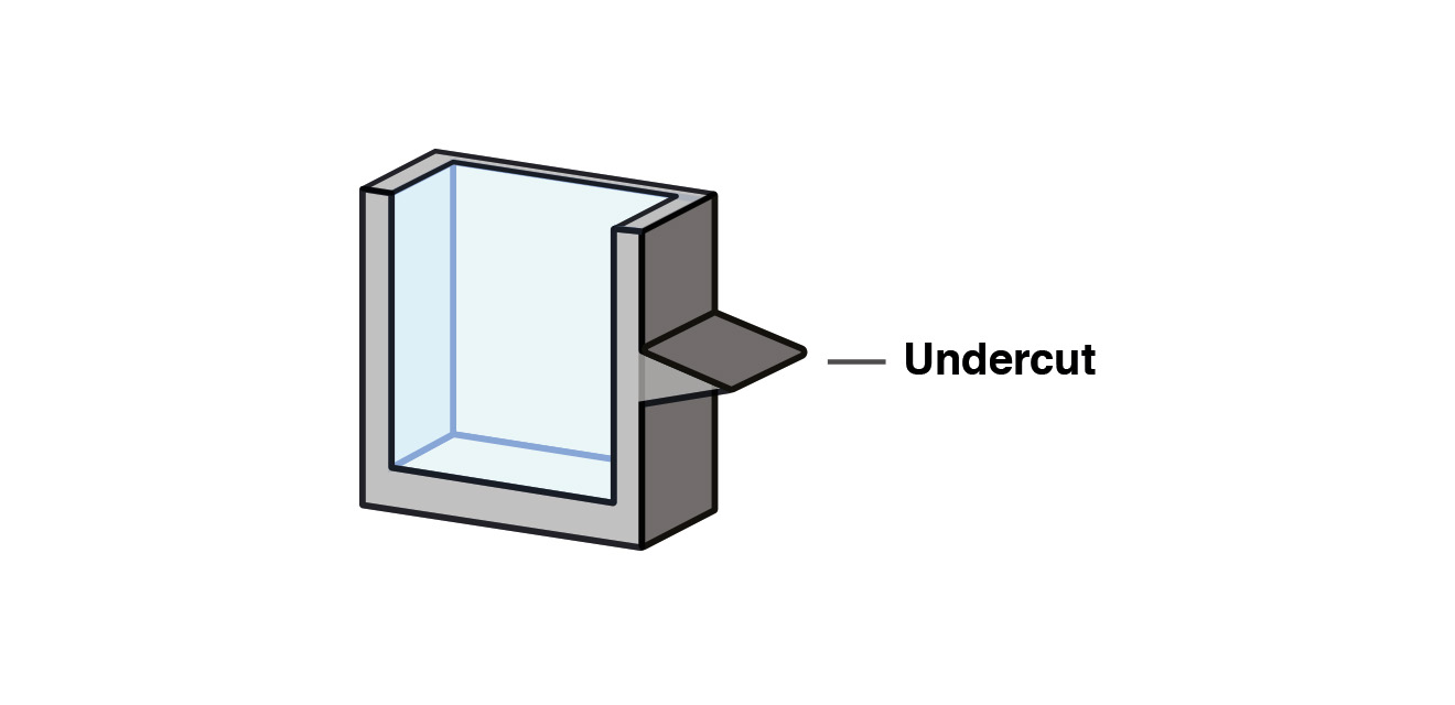
Undercuts prevent easy part ejection, which can lead to damage of the mould or part itself. Hence, such designs are not recommended. If they are a crucial feature of a part, several tooling techniques can be used to produce them effectively. Check out the 5 Ways To Help You Effectively Form Undercuts Guide.
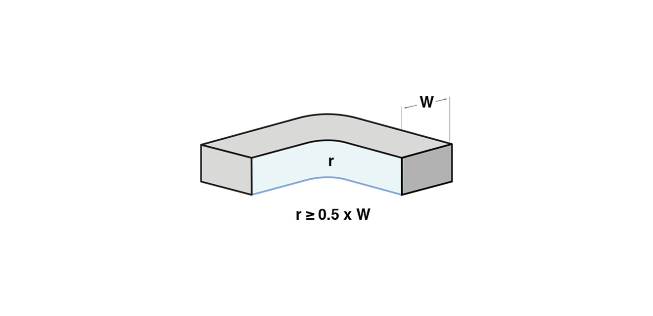
Avoid sharp corners and round all edges. Without the right amount of corner rounding and filleting, part accuracy, strength and aesthetics may suffer. For designs with internal edges, our tooling experts recommend using a radius (r) of at least 0.5 times the wall thickness (W).
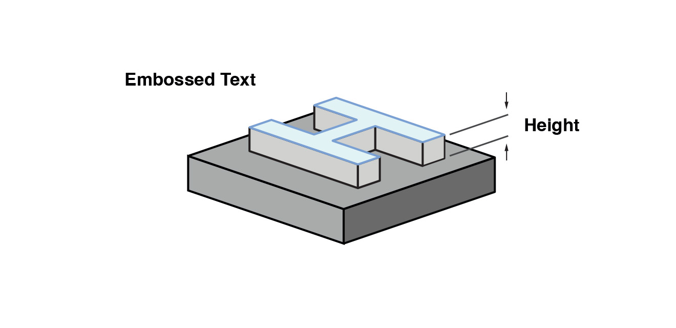
Because a moulded part is essentially the inverse of its machined metal tooling, the rules on engraving/embossing are reversed. For injection moulding, choose embossed over engraved text, as it’s easier to CNC machine them into the mould tool. We recommend a minimum height of 0.5mm to ensure readability. Use a font with uniform thickness and a minimum font size of 20 points for better results.
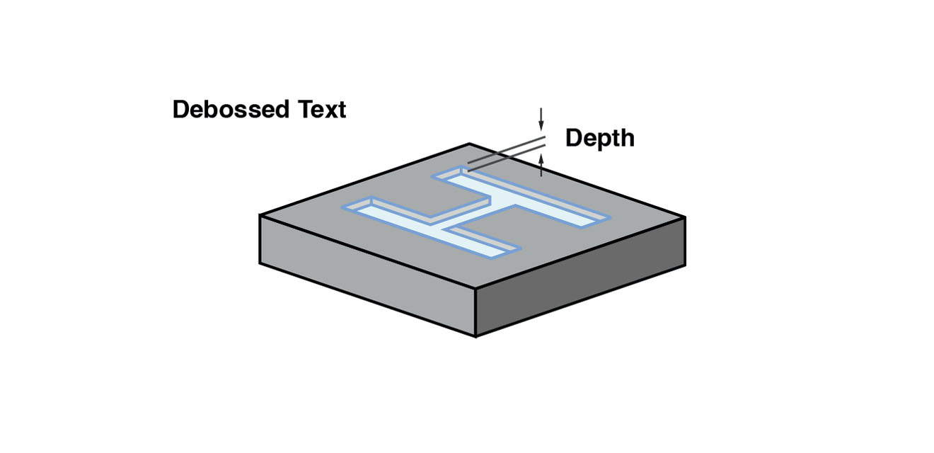
If debossed text is necessary, we recommend using a minimum depth of 1.0 mm and width of 0.7 mm to ensure readability and manufacturability.
| Wall Thickness | 1.2 – 3.0mm is recommended (varies by material) |
| Rib Thickness | Maximum 0.5x of wall thickness |
| Rib Height | Maximum 3x of rib thickness |
| Gusset Thickness | 50 – 60% of nominal wall thickness |
| Boss Wall Thickness | 60% of the nominal wall thickness |
| Boss Height | Maximum 3x of outer diameter |
| Draft Angle | Minimum 2° draft |
| Internal Edges | Minimum 0.5x of wall thickness |
| Embossed Details | Minimum embossing height of 0.5mm; minimum font size 20 px |
| Embossed Details | Minimum engraved height of 1 mm and width of 0.7 mm |

Send your 3D CAD drawing to get a quote and kick off your injection moulding project
When using injection moulding, you have to be prepared to bear the high initial investment associated with making the hard tools. While it is a given that tooling will be costly, there are several ways you can optimize your injection mould design to save on costs:
Use the Injection Moulding Design Guidelines to help design your parts for tooling then export your 3D CAD files in an STEP format. Have your designs ready? Submit your designs now to get a FREE quote. Our team of 3D printing experts are always available to provide on-hand support and recommendations to ensure your parts are ready for moulding.