Undercuts are often seen as a costly feature that can complicate or prevent the release of injection moulded parts. As part of best injection mould design practices, tooling engineers advise to avoid undercuts where possible, or better yet, eliminate them completely. Sounds easy in theory, but in practice it can be tricky, especially if a part needs an undercut to function. When this is the case, it is important that your undercut feature is designed according to a number of recommendations for successful part production.
In this article, we offer a comprehensive guide on undercuts in injection moulding, when they may be necessary, how to create successful undercuts and how to avoid them.
An undercut is a recess surface or protruded feature that prevents a straightforward removal of a part from the mould without any damage. It enables complex features that would be impossible to achieve with a simple two-part mould, but in return, it adds to the cost, mould complexity and cycle time.
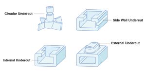
Example of Undercut Features in Injection Moulding Designs
Here are 5 ways that can help you effectively form complex features like undercuts in your plastic moulded part design.
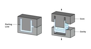
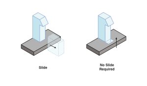
Sometimes the easiest way to address an undercut is to move the mould’s parting line to intersect with the undercut. By dividing the “complex” feature into two halves, you can eject the part without interference from the undercut, making part release easier. It’s worth keeping in mind that parting line placement depends on factors such as part geometry and material flow.
Bump-offs are an excellent choice if you are dealing with flexible and elastic materials like Low-density polyethylene (LDPE) or thermoplastic elastomer (TPE), or if you need a simple solution for a small, mild undercut. Rather than using side actions, in this method, an insert is machined to create a bump-off—a slight undercut in the part design. Once the insert is removed, it leaves behind a ‘wiggle room’ for the part, that allows the part to be safely removed from a straight-pull mould.
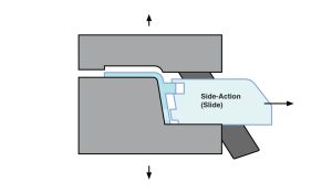
Side actions (sometimes referred to as side pulls) are custom-machined mechanisms added to the mould—guided by pins, cams, or sliders—that slide sideways to form undercut features and retract when the mould opens to release the part. Side actions are an excellent choice for rigid materials—such as nylon, polycarbonate (PC), and acetal (POM)—that won’t stick when the pin retracts, and are especially useful for designs with very deep features.
As the name suggests, hand-loaded inserts are a manual technique whereby metal pieces are placed by the operator in the mould to prevent plastic from flowing into certain areas. While slower than using side actions or bumpoffs, this method is typically ideal for low-volume production, when automation costs cannot be justified, or for internal undercuts that are too complex for automated mechanisms.
Telescoping or sliding shutoffs are mould mechanisms that temporarily block plastic flow in certain areas, allowing undercut features to form when the mould opens. These shutoffs are temporary obstructions that require some creativity. It may involve hooks, clips, or other similar components to block or guide plastic flow to create undercuts, and in many cases can reduce or eliminate the need for side-actions, inserts and bumpoffs that add complexity.
Regardless of the technique used to form undercuts (e.g., side actions, bumpoffs, or shutoffs), it is essential to provide sufficient draft or taper to ensure smooth ejection and prevent scraping during moulding. As a general rule of thumb, a minimum draft angle of 1.5° to 2° is recommended, with an additional 1° for every 25 mm (1 inch) of cavity depth. However, techniques such as shutoffs and bumpoffs often require greater draft angles to accommodate part flexing and to minimize mould wear.
In cases where undercuts are not strictly necessary, try:

Thinking about injection moulding for your next project?
Get in touch and discuss your project with our team.
Looking to produce a custom injection-molded part with undercut features? Simply upload your 3D CAD drawing and specify your quantity, material, and surface finish requirements using our Get a Quote Form. Our engineers will provide a free quote with tailored recommendations to help optimize your part’s production—typically within 48 hours or less.