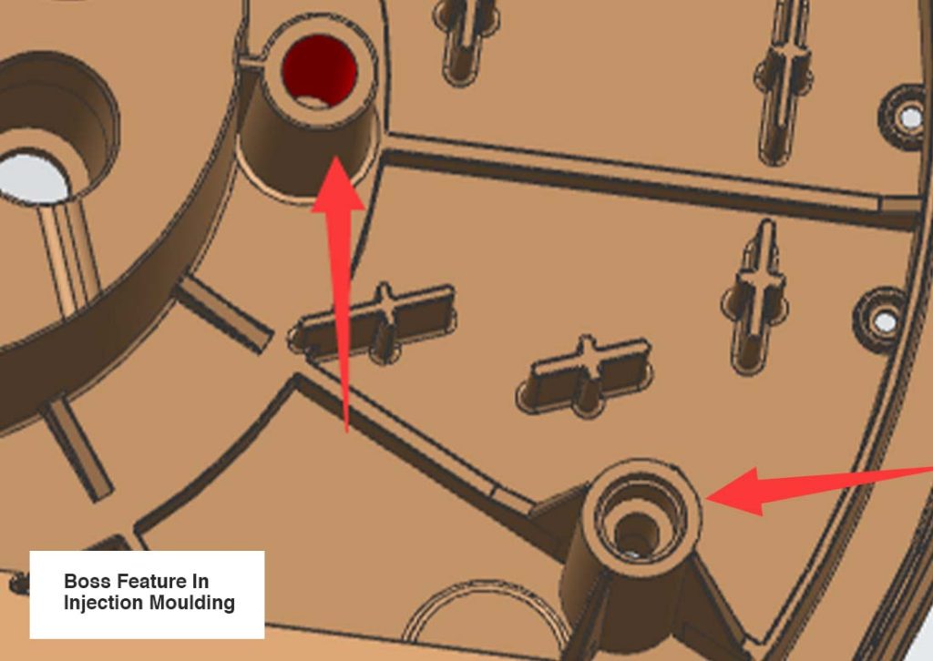
Bosses are protruding cylindrical features (often open-topped), commonly found in plastic injection-moulded part designs. They serve as mounting points or attachment sites for screws, fasteners, or other essential assembly hardware, facilitating mechanical assembly. Plastic bosses perform various functions, including aligning parts, securing fasteners, and reinforcing the structure of the parts.

If your final injection moulded part requires screws or other assembly methods, you will likely need to incorporate bosses into your mould design. To avoid unnecessary cosmetic flaws or defects and fully benefit from the capabilities of boss features, it is important that your injection mould model is designed according to several key recommendations (find them below).
Boss Placement
Screw bosses are continually exposed to stress, so proper placement is crucial for distributing stress evenly across the plastic part. Poor placement can create weak spots, increasing the risk of part failure under load. Some general boss placement rules to follow include:

Boss Wall Thickness
As a general rule of thumb, the wall thickness of a boss should be 60% of the nominal wall to minimize sinking. While bosses should have thick enough walls to provide holding strength for fasteners, especially threaded ones, the walls must not be so thick as to cause sink marks.
Boss Support
The strength of a boss doesn’t only have to come from its wall thickness, it can also be increased by adding gussets and ribs or connecting to a main wall. For standalone or isolated bosses, it’s all the more important to connect it to a sidewall. These extra features improve part strength and durability.
Boss Height
A taller boss does not necessarily equate to more strength; in fact, overly tall bosses can sometimes lead to issues such as increased cooling time or higher stress concentrations. It is recommended that height of boss should be less than 3 times the outer diameter, while still providing at least 60% of the screw thread with something to catch on.
Boss Spacing
If incorporating multiple bosses, it’s recommended to space them out at least 2 times the nominal wall thickness. If the bosses are placed too close to each other, it can create cooling issues during the injection moulding process.

Boss Draft
An appropriate draft of the inner and outer diameter of a boss permits easy withdrawal from the mould and proper engagement with a fastener. The recommended minimum draft for the boss’ inner diameter (ID) is 0.25 degrees or greater, while the recommended minimum draft for the boss’ outer diameter (OD) is 0.5 degrees or greater.
Boss Base Radius
The intersection of the base of the screw boss with the wall is typically stressed. The stress concentration at this intersection increases if no radius is incorporated. To minimize stress concentration, it is recommended to use a radius of 0.25 to 0.5 times the nominal wall thickness at the base of the boss.
Boss Hole Diameter
Providing a radius on the core pin helps in avoiding a sharp corner. This not only helps to mold but also reduces stress concentration. It is recommended that the radius at base of hole in boss should be 0.25 to 0.5 times the nominal wall thickness.
| Boss Placement | Distribute placement Place boss close to thicker walls Place boss on interior area of part |
|---|---|
| Boss Wall Thickness | Should not exceed 60% of the nominal wall thickness |
| Boss Support | Use gussets or ribs or connect boss to a main wall |
| Boss Height | Should be less than 3X the outer diameter |
| Boss Length | Should provide at least 60% of screw thread with something to catch on |
| Boss-to-Boss Spacing | Should be at least 2X the nominal wall thickness |
| Boss ID Draft | 0.25 degrees or greater |
| Boss OD Draft | 0.5 degrees or greater |
| Boss Base Radius | Should be 0.25 to 0.5X the nominal wall thickness |
| Boss Hole Radius | Should be 0.25 to 0.5X the nominal wall thickness |
Use the Injection Moulding Boss Design Guidelines and Tips above to help design your parts for manufacturing then export your 3D CAD files in an STEP format. Submit your drawings to our site contact form and our engineering team will get back with a quote and comprehensive DFM (design for manufacturing) feedback.
Discover more design guides for better moulded parts:
How to Design Ribs for Injection Moulding
Injection Moulding Defects and Solutions
Choosing a Gate Type for Injection Moulding
